Define the output-filter position
The product description covers AC filtering and high-frequency harmonic processing. When enquiring, identify the position of the capacitor in the output filter and provide the waveform and current requirement at that position. The converter name or total output power is useful context but should accompany the component-level requirement.
The resin filling is described with a UL94 V-0 material rating. For the PCB interface, request the body outline, lead pitch and lead diameter for the selected rating. A two-pin or four-pin description alone does not specify the complete footprint.
AC ratings and temperature derating
The rated-voltage options at 85°C are 250, 310, 350 and 400 VAC. Capacitance tolerances are J (±5%) and K (±10%). Request the specific voltage, capacitance and package combination needed for the design; the headline ranges do not promise every possible combination.
The specified case-temperature range is −40°C to +105°C. Between 85°C and 105°C, operating voltage is derated by 1.5% per degree relative to rated voltage at 85°C. The catalogue operating-life statement is 60,000 hours at rated voltage and 85°C. Those conditions should accompany the figures in a component comparison.
Humidity performance under a defined exposure
The biased humidity test is specified at 60°C and 95% relative humidity for 1,000 hours with rated voltage applied. The stated acceptance limits include absolute capacitance change no greater than 5% and insulation resistance no lower than 50% of the initial limit.
If the equipment has a particular qualification requirement, include the required procedure and acceptance limits with the enquiry. Ask for the applicable evidence for the proposed configuration. The catalogue exposure describes a defined test rather than a general waterproof rating or a life prediction for every enclosure environment.

A 250 VAC example for the footprint review
In the 250 VAC RMS group at 85°C, the 3.0-microfarad example has a width of 32.0 mm, height of 24.5 mm and thickness of 15.0 mm, each with a ±1 mm tolerance. Its lead pitch is 27.5 ±0.5 mm and lead diameter is 0.8 ±0.05 mm.
That row lists a voltage-transition rate of 50 V per microsecond, ESR of 9.0 milliohms at 10 kHz and RMS current of 6.5 A at 85°C and 10 kHz. Keep the frequency and temperature labels attached to these values. Another capacitance or housing requires its own row; the example is not a series-wide current rating.
Prepare the filter-capacitor enquiry
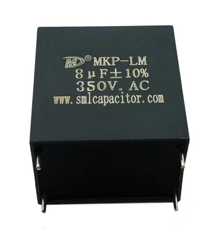
Compare the AC filter capacitor range to review related products. For a board-mounted MKP-AM request, send capacitance, tolerance, voltage waveform, current requirement and operating temperature with the drawing. Identify the operating mode associated with any measurements you supply.
The capacitor RFQ checklist provides a starting point for sample and production requests. Include the preferred lead arrangement, maximum body envelope, quantities and required documentation. Ask for the electrical data and outline of the proposed part together before evaluating the sample in your filter assembly.
Frequently asked questions
Where is MKP-AM used?
The listed applications are output AC filtering in power converters, UPS equipment and motor drives.
Does the 105°C limit permit full rated voltage?
Voltage derating is specified between 85°C and 105°C at 1.5% per degree relative to rated voltage at 85°C.
What should accompany a PCB sample enquiry?
Send the required rating, waveform and temperature conditions together with the lead pitch, body envelope and drawing. Identify the sample quantity and required documents.
Sources & technical reading
Product information is based on the SMILER catalogue. Confirm the specification for the selected configuration.