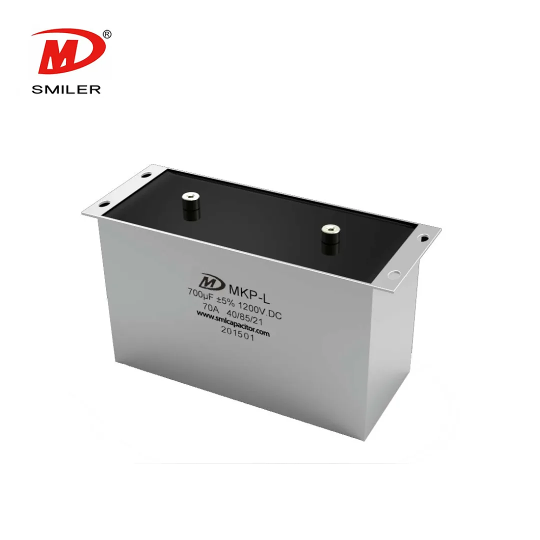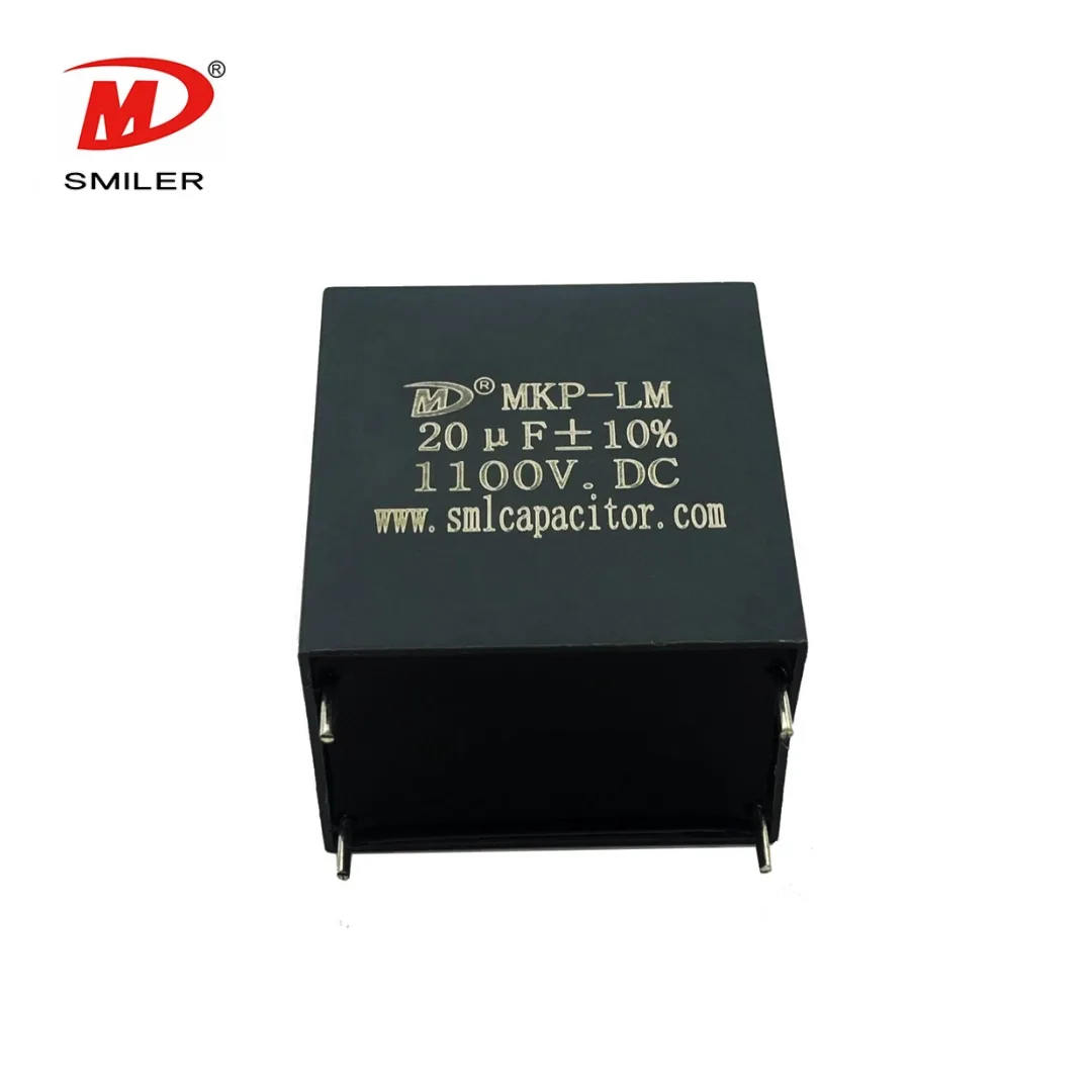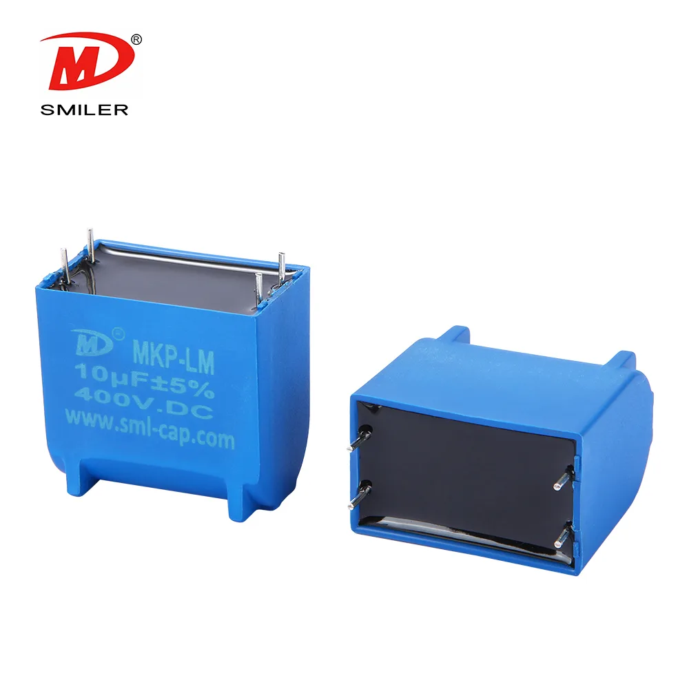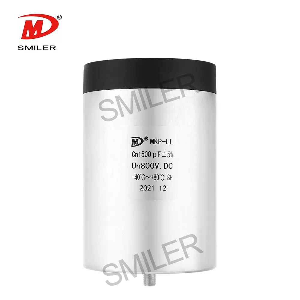
Applications and series selection
The application list includes wind and solar inverters, electric and hybrid vehicle equipment, welders, elevators and motor-drive systems. Low ESR, low inductance, ripple-current handling and self-healing behavior are identified features. The voltage and capacitance ranges describe the family; request the data for the particular combination you need.
If you are evaluating a film capacitor in place of an electrolytic DC-link component, provide the existing requirement and circuit conditions. The proposed capacitance, voltage duty, current duty and connection arrangement should be reviewed together, rather than treating a matching voltage label as proof of interchangeability.
Housing dimensions affect the temperature specification
For housing diameters up to 116 mm, the specified hotspot limit is 85°C. For the 136 mm diameter version, the hotspot limit is 80°C. Both groups have a stated lower operating temperature of −40°C. Keep the diameter distinction when selecting a configuration for an enclosure.
The catalogue expected-life statement is 100,000 hours at rated voltage and a 70°C hotspot. This is a conditional component statement, not a warranty term for an inverter. Include the temperature basis of your application data so the proposed part can be reviewed against the relevant thermal conditions.
Voltage tolerance and temporary excursions
Capacitance tolerance choices are J (±5%) and K (±10%). The terminal-to-terminal test is 1.5 times rated voltage for 10 seconds at 20°C ±5°C. That test is separate from the operating rating and from the temporary overvoltage schedule.
The schedule allows 1.1 times rated voltage for 30% of on-load duration, 1.15 times for 30 minutes per day, 1.2 times for five minutes per day and 1.3 times for one minute per day. Each multiplier belongs with its duration; none is a replacement continuous voltage rating. State the expected excursions in the application brief instead of selecting solely from the largest multiplier.
The reference-standard field lists GB/T 17702 and IEC 61071. Where your project requires a particular test report or approval document, specify it in the enquiry and request the scope applicable to the proposed capacitor.
Terminal and mounting details
The maximum terminal torque is 5 N·m for M6 and 6 N·m for M8. The separate installation-torque entry is 10 N·m. Match each value to the correct interface in the assembly instructions; a mounting limit is not automatically a terminal-tightening limit.
Male and female terminal options are listed, and the installation entry permits any position. The specification gives a maximum altitude of 2,000 m. Include the connection drawing, available envelope and installation conditions in your enquiry so the chosen configuration can be identified completely.
Request a DC-link capacitor proposal
Browse the DC-link capacitor range or consider the custom MKP-L series if your project calls for a design around specific voltage and capacitance requirements.
For MKP-LL, send the normal DC voltage, temporary voltage conditions, required capacitance, tolerance and ripple-current information. Add the local thermal conditions, terminal preference, drawing and quantities. The capacitor RFQ checklist helps keep the electrical requirement and mechanical interface in one request.
Frequently asked questions
Is the hotspot limit always 85°C?
No. It is 85°C for diameters up to 116 mm and 80°C for the 136 mm diameter version.
What is the published life condition?
The expected-life statement is 100,000 hours at rated voltage with a 70°C hotspot. It is not an unconditional service-life guarantee.
Are all voltage and capacitance combinations offered?
The figures describe the series range. Request the individual data and drawing for the combination your equipment requires.
Sources & technical reading
Product information is based on the SMILER catalogue. Confirm the specification for the selected configuration.