Pulse applications and construction
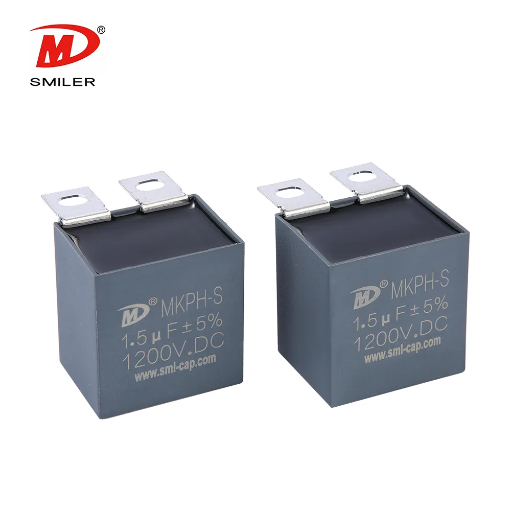
The series is described for IGBT buffer circuits and industrial control equipment. Its features include pulse capability and self-healing behavior. The resin filling carries a UL94 V-0 material description. Provide the actual snubber position and pulse requirements when requesting a configuration.
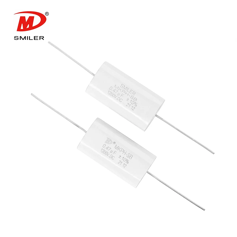
The snubber capacitor range also includes the MKPH-LS family, which has a different housing and lead description. Compare those interfaces against your assembly drawing rather than treating similar model names as equivalent parts.
Temperature and operating-life conditions
The case-temperature range is −40°C to +105°C. Between 85°C and 105°C, the specified voltage derating is 1.33% per degree relative to operating voltage at 85°C. The rated-voltage range and this temperature condition should be reviewed together.
The operating-life statement is 100,000 hours at rated voltage and a 70°C hotspot. It is a conditional catalogue statement, not a warranty period or an assurance for any switching waveform. Include your temperature conditions and the operating modes that define the intended pulse duty in the enquiry.
Electrical tests and insulation requirements
Capacitance tolerance options are J (±5%) and K (±10%). The terminal-to-terminal DC test is 1.5 times rated voltage for 10 seconds. A separate terminal-to-case test is specified at 2,100 VAC and 50 Hz for 10 seconds. These are test conditions rather than alternative continuous voltage ratings.
For capacitance at or below 0.33 microfarads, insulation resistance is specified at no less than 100,000 megohms. Above 0.33 microfarads, the insulation-resistance and capacitance product is at least 30,000 seconds. The accompanying conditions are 20°C, 100 VDC and one minute. Keep the capacitance threshold and test conditions with the applicable requirement.
The specified climatic category is 40/105/56. Include any project-specific environmental qualification requirement with the sample enquiry, and request the applicable documentation for the selected part rather than assuming it from the category alone.

Terminal outlines and a specific data example
The outline drawings identify Types A and C with an M6 mounting-hole designation and Types B and D with M8. Choose the complete outline, including the connection spacing and body dimensions, rather than selecting by the hole designation alone.
In the 1,000 VDC group, the 1.00-microfarad example is 42.5 mm wide, 28 mm thick and 37 mm high, with ±1 mm tolerances. Its specified voltage-transition rate is 500 V per microsecond and peak current is 500 A. The same row gives ESR of 4.1 milliohms at 100 kHz, RMS current of 15.8 A at 10 kHz and 60°C, and inductance no greater than 25 nH. These figures describe that row, not every MKPH-S.
Send a switching-duty enquiry
Use the capacitor RFQ checklist to prepare capacitance, tolerance, voltage behavior, pulse shape, repetition conditions and thermal information. Attach the assembly drawing and indicate the terminal type you are considering.
For a replacement, provide the original specification and explain which interfaces must remain unchanged. For a new design, identify any dimensions still open to adjustment. Add sample and production quantities, then request the proposed part data and mechanical outline together for review.
Frequently asked questions
What applications are listed for MKPH-S?
IGBT snubbing and switch-mode power supplies are the stated applications. Supply the waveform at the intended snubber position.
What terminal-hole options are shown?
Types A and C are designated M6; Types B and D are designated M8. The full drawing is needed to establish the rest of the interface.
Are the peak and RMS current values interchangeable?
The table gives separate peak-current and RMS-current fields. Retain the stated frequency and temperature conditions when reviewing the RMS value.
Sources & technical reading
Product information is based on the SMILER catalogue. Confirm the specification for the selected configuration.